Results
Specifications
Our original specifications were as follows:
- One frequency output is controlled continuously with gyroscope, and frequency increases with rotational velocity
- Based on keypad input, 8 distinct frequencies can be played within 1% accuracy
- Frequency output from gyroscope and keypad are played at the same time
- Volume can be adjusted continuously
- Low and high pass filters function with cutoff frequency that can be adjusted continuously
- LPF has a cutoff frequency between 8 kHz and 12 kHz, with a resolution of 2.5 kHz (within 10% accuracy)
- System can handle frequencies from 60 Hz to 1100 Hz
At the midpoint checkoff, we re-scoped the project to eliminate the last 3 specifications. Of inital specifications, we achieved enough for proficiency. We were able to read the velocity of the gyroscope, read the value of a continuous range of voltages using a potentiometer + voltage divider and the ADC, and play 8 distinct frequencies based on keypad input within 1% accuracy. However, we did not get to the point of driving a speaker based on the rotational velocity of the gyroscope, nor did we get to interpret the reading of the ADC to control the volume. That being said, we had all of the building blocks for our design, at least on the MCU side.
MCU Timing
The MCU SystemClock is configured based on the PLL, which is configured to run at 40 MHz. The ADC uses the SystemClock, and SPI uses the APB2 clk with the baudrate configured to be 1 MHz. The gyroscope and analog-to-digital converter (ADC) were both read using polling every 500 ms (i.e. at 2Hz). This was based on Timer2 of the MCU. If we got to the point of driving another speaker with the gyroscope reading, the frequency would have likely been increased until the speaker’s output frequency was appropriately responsive to changes in gyroscope velocity. However, since the sampling frequency for the gyroscope reading and the ADC didn’t need to be terribly high, polling was adequate. Had more frequent sampling been required, we could have implemented interrupts or direct memory access.
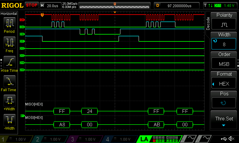
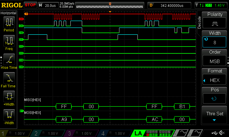
Gyro SPI
The gyroscope reading printed to the terminal reflected changes in rotational velocity along the x, y, and z axes. SPI transactions verifying these readings are shown below:

Gyroscope reading demonstration:
MCU Frequency output
The audio freqiency output, chosen from 8 options based on which key of the keypad is pressed, were measured with a RIGOL MSO1104 oscilloscope. The results were as follows:
- C4: 261 Hz desired, 263 Hz actual
- D4: 294 Hz desired, 294 Hz actual
- E4: 330 Hz desired, 312 Hz actual
- F4: 349 Hz desired, 333 Hz actual
- G4: 392 Hz desired, 385 Hz actual
- A4: 440 Hz desired, 417 Hz actual
- B4: 494 Hz desired, 500 Hz actual
- C5: 523 Hz desired, 500 Hz actual
The accuracy of the frequencies varies by note, and some notes are outside of the desired 1% accuracy window. Part of this may be due to the measurement method – we had a difficult time eliminating 60 Hz noise from the output, so we ended up using the oscilliscope’s built-in high pass filter. This may have caused some error in the frequency measurements. It is likely that the frequency measurements were not completely accurate since B4 and C5 on the keypad do sound distinct, but they had the same frequency reading. That being said, to achieve more accurate frequency outputs, we could have reconfigured our timer ARR and PSC values to support a higher degree of precision.
Keypad digital audio synthesis demonstration:
ADC output
The ADC output was printed to the terminal as the potentiometer in a simple voltage divider circuit was adjusted. With a resolution of 6 bits, the ADC output spanned from 0-63 as the voltage into the analog pin spanned from 0-3.3V. This value was updated every 500ms through polling, although this could have been made more frequent.
Potentiometer analog-to-digital converter reading demonstration: