MCU Design
MCU Design Plan
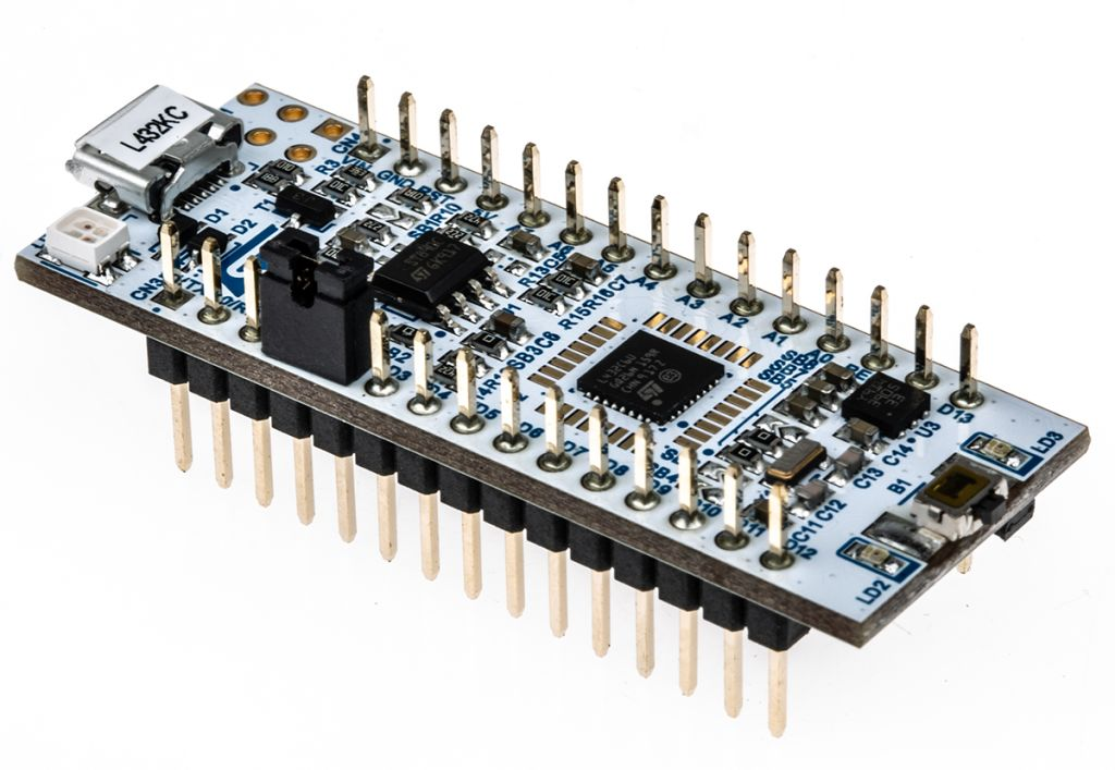
The goal of this project was to use the STM32 Nucleo-32 board with an STM32L432KC Microcontroller (MCU) to handle all the user inputs and determine the frequency of sound to be played through two speakers. The MCU will take multiple inputs, interpret their data and communicate with the FPGA to generate the desired audio output. All relevant information is communicated from the MCU to the FPGA over SPI.
The project has three inputs:
8-Key Keypad

The keypad is read through the MCUs GPIO pins, with each key functioning as a switch. The key presses are debounced, and only one key is allowed to be pressed at a time. The 8 keys correspond to a C major scale starting at middle C (C4) to C5 with each key mapped to a specific note in the scale. The MCU determines the output frequency based on the key pressed.
A3G4250DTR Gyroscope
The 3-axis digital gyroscope measures angular rotation around three axes. The gyroscope outputs 16 bit angular rate data (sent as two 8-bit values) over SPI to the MCU. The MCU reads this data and converts it into a corresponding frequency, which can then be sent to the FPGA.
10k Ohm Potentiometer
The potentiometer outputs an analog voltage, which the MCU reads using its onboard ADC. This voltage is used to determine the cutoff frequency for a digital filter implemented on the FPGA.
Signal Generation
A pin on the MCU is connected to a timer of one of the two desired frequencies, and the timer is switched at a frequency fast enough so the resulting signal sounds like the sum of two, but slow enough so that the FPGA can successfully sample the two frequencies.
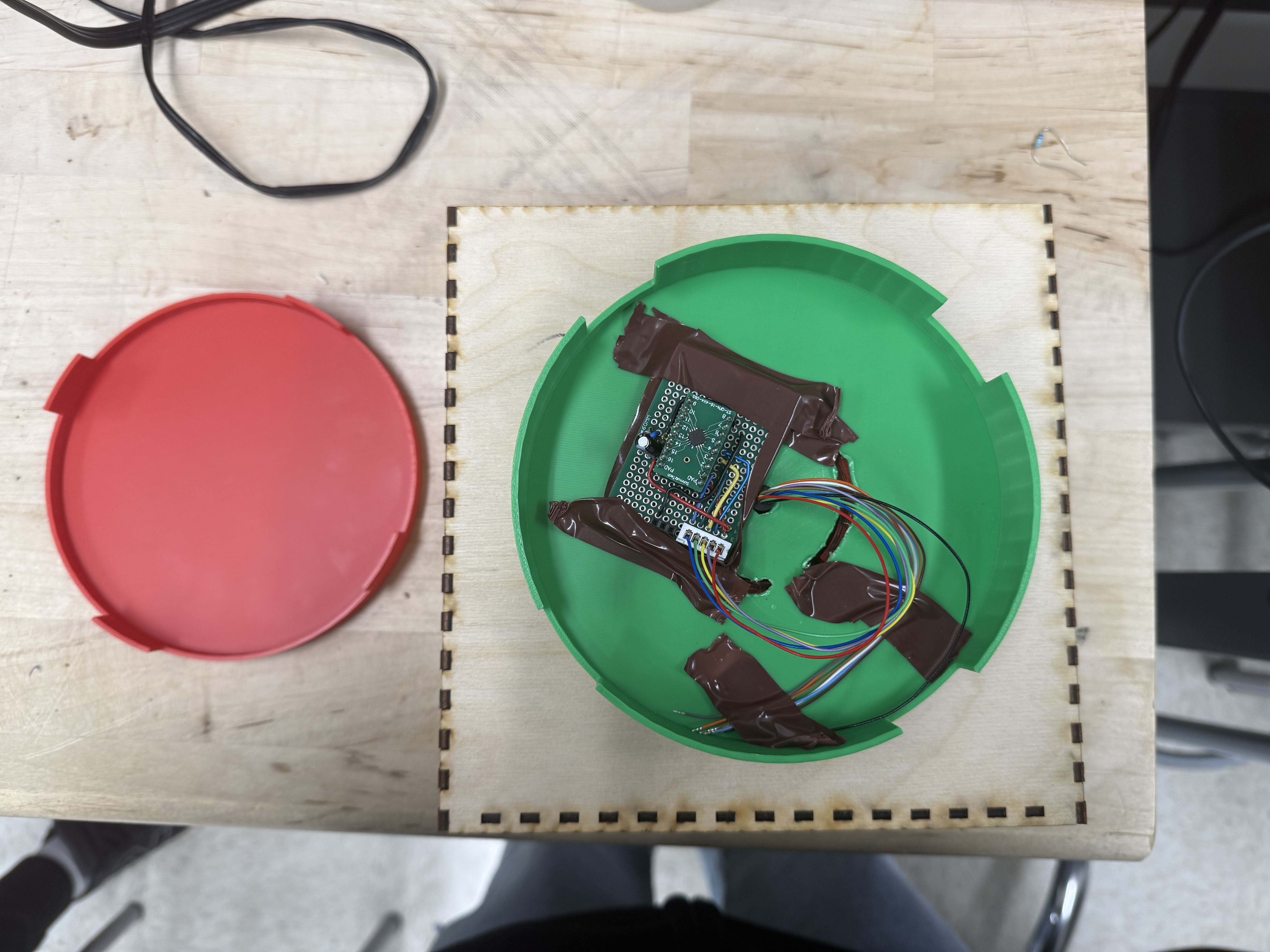
MCU Design reality
In this project, we were able to build an 8-key keypad for users to interact with. It operates as described, each key corresponding to a note in the C-major scale from middle C (C4) to C5. We initially planned to transfer this information from the MCU to the FPGA over four wires, since only a small amount of data needed to be sent. However, we ultimately decided to drive a speaker directly from the MCU by generating a square wave at the corresponding frequency for each key press. The MCU was also able to read data from the A3G4250DTR gyroscope and we were able to display the angular rotation readings on the MCU. Finally, we read the analog voltage from a 10 kΩ potentiometer using the MCU’s onboard ADC, which could be used to adjust filter parameters or other project functions.