Hardware
New Hardware/Components Description
The new hardware used in this project is a Digital-to-Analog Converter (DAC), Slip Ring, and Gyroscope
DAC (MCP4725)

The DAC used in the project is the MCP4725, a single-channel 12-bit DAC with an integrated output buffer and on board nonvolatile EEPROM. It communicates using a two wire I2C interface. In our project the goal of the DAC was to communicate with the FPGA using I2C where the FPGA acts as the I2C primary device and the MCP4725 functions as the secondary device. THe FPGA would send a digital waveform to the DAC, which would convert it to an analog signal to drive a speaker. We had initially planned to use two DACs, each driving a speaker, to make two different sounds. However we were not able to get I2C communication working on the FPGA, and therefore the DACs could not be used in the final result of the project.
The DAC is new hardware for the team, as we had not previously worked with digital to analog conversion or used a DAC to generate analog signals for sound output. In Lab 4, we had generated a square wave frequency and played sound through a speaker, but that was purely digital and did not involve analog waveforms. Additionally, we had not worked with I2C before.
Slip Ring (1528-1176-ND)
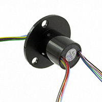
The slip ring used in this project was the 1528-1176-ND, a 22 mm rotary gold plated slip ring designed for 12 wires. It has 12 color coded 28 AWG wires, each capable of carrying up to 2 A at 240 VAC or 240 VDC. The slip ring also includes a 44 mm diameter flange with mounting holes and is rated for rotational speeds up to 300 RPM. The primary goal of the slip ring in this project was to provide a reliable electrical connection between the spinning gyroscope and the MCU. Because the gyroscope would be rotating, a standard wired connection would work. The slip ring enabled continuous data transfer while the sensor was in motion and we were able to get the gyroscope and slip ring reading data to the MCU.
The slip ring was new to the team, as we had not previously used this type of rotating electrical connection. Working with it required consideration of noise, since slip rings can introduce electrical noise into measurements. In our project, the slip ring did introduce some noise, which required careful handling in the circuit and software to ensure accurate gyroscope readings.
Gyroscope (A3G4250DTR)

The gyroscope used in this project was the A3G4250D, a 3-axis angular rate sensor capable of measuring rotational motion with a full scale range of +/- 245 degrees per second. It provides 16 bit rate output data and 8-bit temperature reading through either an SPI or I2C digital interface. In this project, the gyroscope was configured to communicate over SPI, with the goal of it outputting 16 bit angular acceleration data to the MCU for use in later frequency calculations. Our project successfully achieved this functionality. The gyroscope was able to measure angular velocity, convert it to a 16-bit digital output, and transmit the data to the MCU reliably over the SPI bus. This data was then used by the MCU in frequency computations.
The A3G4250D was new hardware. Prior coursework involved working with SPI and a simpler temperature sensor, but this project required us to go further by interpreting angular rate data and implementing continuous real time data capture over SPI.
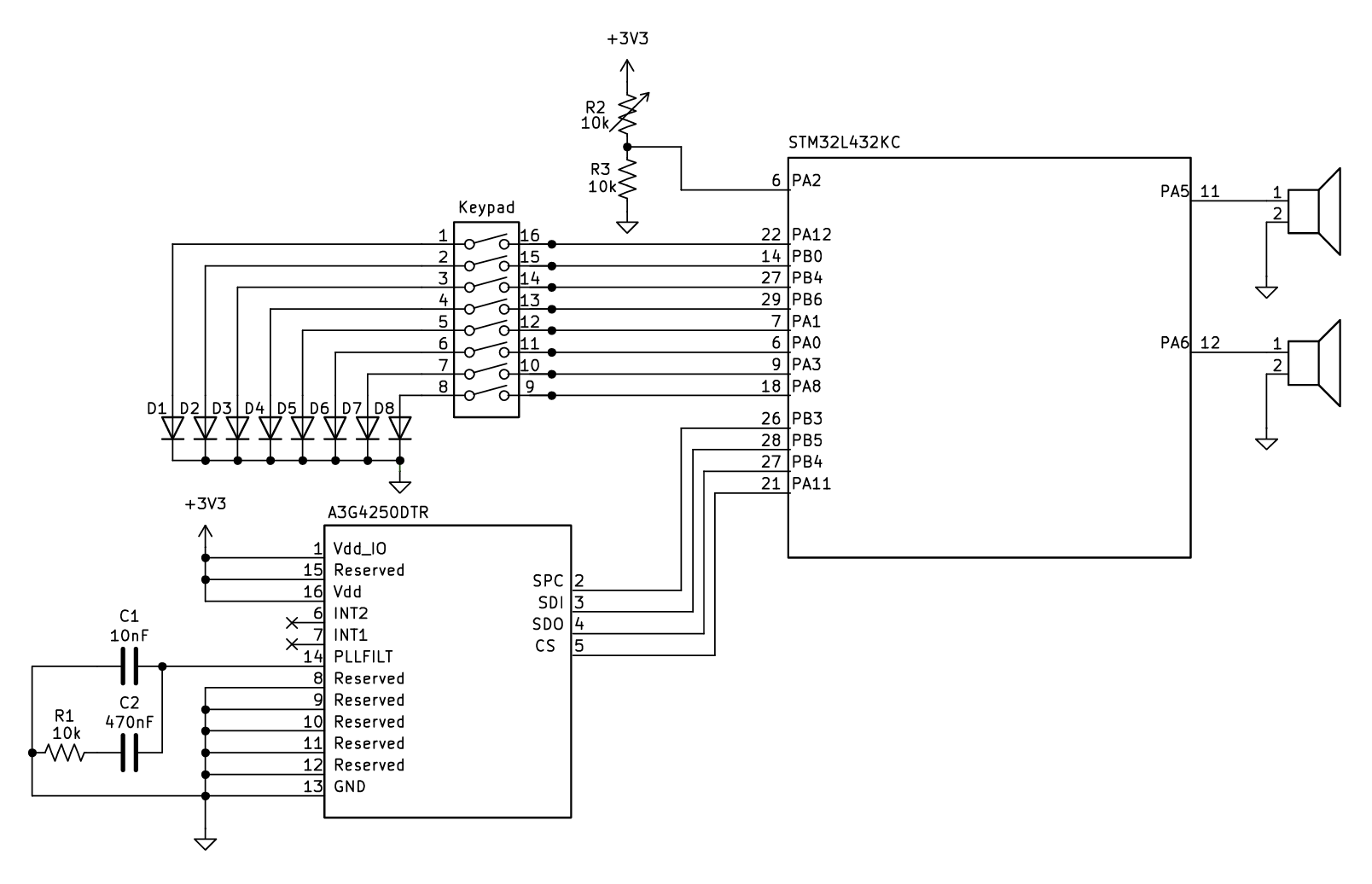
Circuit Diagram
Below is the circuit diagram for our project. The keypad was implemented with 8 mechanical switch keys, represented in this schematic by a switch bank. Had we gotten to fully implement our FPGA design, 6 additional GPIO pins on the MCU would be used to transmit input data to the FPGA for processing.
BOM
| Item | Part Number | Quantity | Price (Raw) | Shipping | Total Price (w/ Tax) | Purpose |
|---|---|---|---|---|---|---|
| Gyroscope | A3G4250DTR | 1 | 15.98 | 5.99 | 21.97 | Wheel |
| 12-wire Slip Ring | 1528-1176-ND | 1 | 9.99 | 0.97 | 10.96 | Wheel |
| DAC | MCP4725A1T-E/CH | 4 | 5.08 | – | 5.08 | Driving speaker |
| SMD adapters | – | 3 | stockroom | – | – | Mounting DAC & gyro |
| Potentiometer (volume) | – | 1 | stockroom | – | – | – |
| Capacitors, resistors | – | 5 | stockroom | – | – | – |
| Speaker w/ amplifier | – | 2 | digital lab | – | – | – |
| Mechanical switch keys | – | 8 | makerspace | – | – | Keypad |
| Plywood | – | 1 | makerspace | – | – | Wheel housing |
| 4 wood screws | – | 4 | stockroom | – | – | Wheel housing |
| PLA | – | 8 | makerspace | – | – | 3D print wheel/keycaps |
Summary
| Description | Amount |
|---|---|
| Pre-tax cost | 31.05 |
| Shipping | 6.96 |
| Total | 38.01 |
Housing
Below is the mechanical housing we built for the gyroscope and slip ring. The top part (the red and green cylinder) spins and has room for a soldered PCB inside. The bottom wooden box also has space for breadboards.